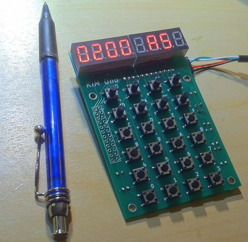
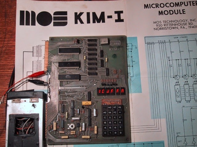
Of all the PDP-8s, the 8/I is my favourite. Alas, getting a real one is impractical: they are pretty much impossible to obtain, and just as hard to maintain once you've found one. But asI learned from my
$15 KIM-1 clone, making a replica is a good way to get involved with the inner guts of a vintage machine too. The idea of the PiDP-8 is to make it an open-source hardware project again. So here I go... work in progress, comments welcomed.
![]() |
| First completed prototype as of March 30, 2015 |
Note: below is the development blog in all its gory detail. The permanent web site for the PiDP is slowly but surely emerging here (link).Introduction
The picture to the left shows the state of affairs in early January. Shown on top is the front panel artwork, made translucent in this picture to reveal:
(a) the PCB behind it - mostly visible in the dimmed LEDs, and
(b) a real PDP-8/I front panel behind that - mostly visible in the lit LEDs.
The front panel is pretty much a pixel-perfect clone of the original, with one notable exception: I chopped off the leftmost part of the original, which contains no operating components.
13 Januari 2015
As I looked around for the bits and pieces that I'll need for the PiDP, the last few weeks have crystallised what I want, and what is feasible. The hardest part is always to settle on the compromises you can accept, given the budget you want to work on. To me, a low-cost kit is far more interesting than a no-compromise $1000 replica.
From the cosmetic side, these are the points I've settled upon:
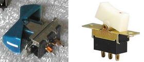
- switches: for a PDP, switches are everything. The original ones for the 8/I are not available. I've settled upon the kind of 120V/240V toggle switch you normally use in wall-mounted light switches. They don't cost all that much, have the right proportions and have a nice tactile feel to them.
![]() |
| Switches... Original 8/I switches on the left (although different in colour). On the right, the budget alternative. Not authentic, but nice and cost-effective. Design Choice #1 is made... |
![]() |
| Lining up some of these switches to see how they'd look on a front panel. |
- scale: a real 8/I is the width of a 19" rack. In the end, the size of the switches I selected determined the scale of the replica overall. A real 8/I has switches of 1.5cm in width. The switches I selected are 1.0cm in width. To make everything in proportion, the replica is downsized 2:3 versus the original, and is still comfy to toggle on.
- front panel: getting a front panel machined from a specialist shop is very very expensive. The alternative: photos printed on acrylic. An acrylic panel where everything that's supposed to be white is left transparant. I'll have to glue a white paper mask behind it (to let the white lettering come out) but cut-outs from the mask will show the LEDs on the (black) PCB behind it. I'll probably add some 35% black pattern as shading on the front panel above the LEDs.
On the electronics side, this is a very straightforward project. A microcontroller runs one of the existing PDP-8 emulators, and a front panel PCB is attached to the microcontroller to contain the LEDs and switches.
- schematic: I took the schematic idea from my KIM Uno project. In one sense, a KIM-1 does not differ too much from a PDP-8/I front panel. The 8/I has 26 switches, the KIM-1 has 24 keys. The 8/I has 92 LEDs, the KIM-1 has 49 segment LEDs. The multiplexing logic of the KIM Uno just needs some added rows and colums for extra LEDs.
- PCB design: A row of 26 switches requires at least 26cm in board space. Round that up to the nearest standard PCB size, and you end up with a 30cm board width. And, as it turns out, reproducing all the LEDs in the right place demands a 10cm height. The PCB is an unsophisticated thing: 92 LEDs, 26 switches, and a bunch of resistors to control LED brightness. As the microcontroller I chose has fairly weak outputs, I put a UDN2981A in-between to take the load off the MCU. And to avoid 'ghosting' of switches, which is a problem with matrix keyboards, every switch needs a diode in line with it. Lots of parts, but the cost is only a few cents for most of them.
![]() |
| PCB front (LEDs and switches) and PCB back (with the RPi GPIO connector top right). |
. - Microcontroller choice: the original idea was to use a Teensy 3.1 with Bill Haygood's emulator. ARM core, 96K RAM, it would have sufficed. Except that it proved a very tight fit. Because 32K of the PDP's 12-bit words end up taking 64K of 8-bit RAM; packing 3 PDP words in 4 bytes is too cumbersome.
So I looked around for the cheapest alternative. An Arduino Due would do it, but the Raspberry Pi B+ was more attractive. Not much more expensive at $35, and it has all the connectors on-board already. SD drive, HDMI for the terminal, USB ports (USB sticks will act as floppy disks and as the paper tapes): as an all-in-one package it makes sense. Plug it in to the front panel PCB through its 40-pin GPIO connector and that's it. Even though it's more a microcomputer than a microcontroller. Accepting a Raspberry Pi also meant I could use the brilliant simh as the emulator core - which I believe is the most competent PDP-8 emulator around.
The software part has not fully matured yet:
- simh compiles and runs fine on the Raspberry Pi. But I need to insert the code to update the LEDs and scan the switches. So far, I've experimented with adding a parallel thread to simh which just sticks the PDP-8 registers into the GPIO pins every 5ms or so. That works fine as a test (see 16 January entry below), but:
- Linux is a bad choice for real-time programs. Multiplexing 8 rows of 12 LEDs each is simple enough on an Arduino - microcontroller software has no problem with flashing each LED row fast enough so that the human eye does not notice any flickering of the LEDs. But Linux is not made for real-time programs. Still, it seems I can update each of the 8 LED rows 30 times per second without too much interruption of the Linux task scheduler.
- I can't say I've mastered the whole source code of simh, just enough to test my ideas a bit.
Development file repository:
I'll post updates more or less regularly
here. Just mail me for the access code.
16 January 2015
The software part is slowly taking shape. It breaks down in two parts:
- Driving the front panel: means getting RPi code that displays the register settings on the 92 LEDs and scans the 26 keys. It is going to be much simpler than I thought.
![]() |
| Driving 8 rows * 12 LEDs flicker-free under Linux is not a problem! |
I had expected a lot of flickering from the thread being interrupted by other processes. Not so - as long as you use pthread_setschedparam() to set the multiplexing thread to a high priority. I guess I did not realise quite how fast modern computers are :).
Anyway, a small breadboard setup proves I can get the LEDs to be multiplexed without noticeable flickering. A stand-alone test program (outside of simh) now runs a high-priority thread, which drives 1 led row reliably for 4ms, 30 times per second, whilst the other thread just does whatever it wants to do (ie, it should run simh). - Hooking up simh with the above multiplex driver. Getting register values out of simh, to display them on the front panel, seems to work fine. But getting front panel key presses communicated in to simh, and letting simh do the appropriate action based on it, is a challenge I have not looked in to yet.
20 January 2015
PCBs ordered at Elecrow... always a stressful moment. What stupid mistakes did I make?
Also, I found the right supplier for the acrylic front panel, but have not ordered it yet.
24 January 2015
Elecrow finished the boards... just a few more days before they arrive. I just realised I have nowhere near enough LEDs in the spares box. Oh well. I'll have to test with only half the LEDs for a while.
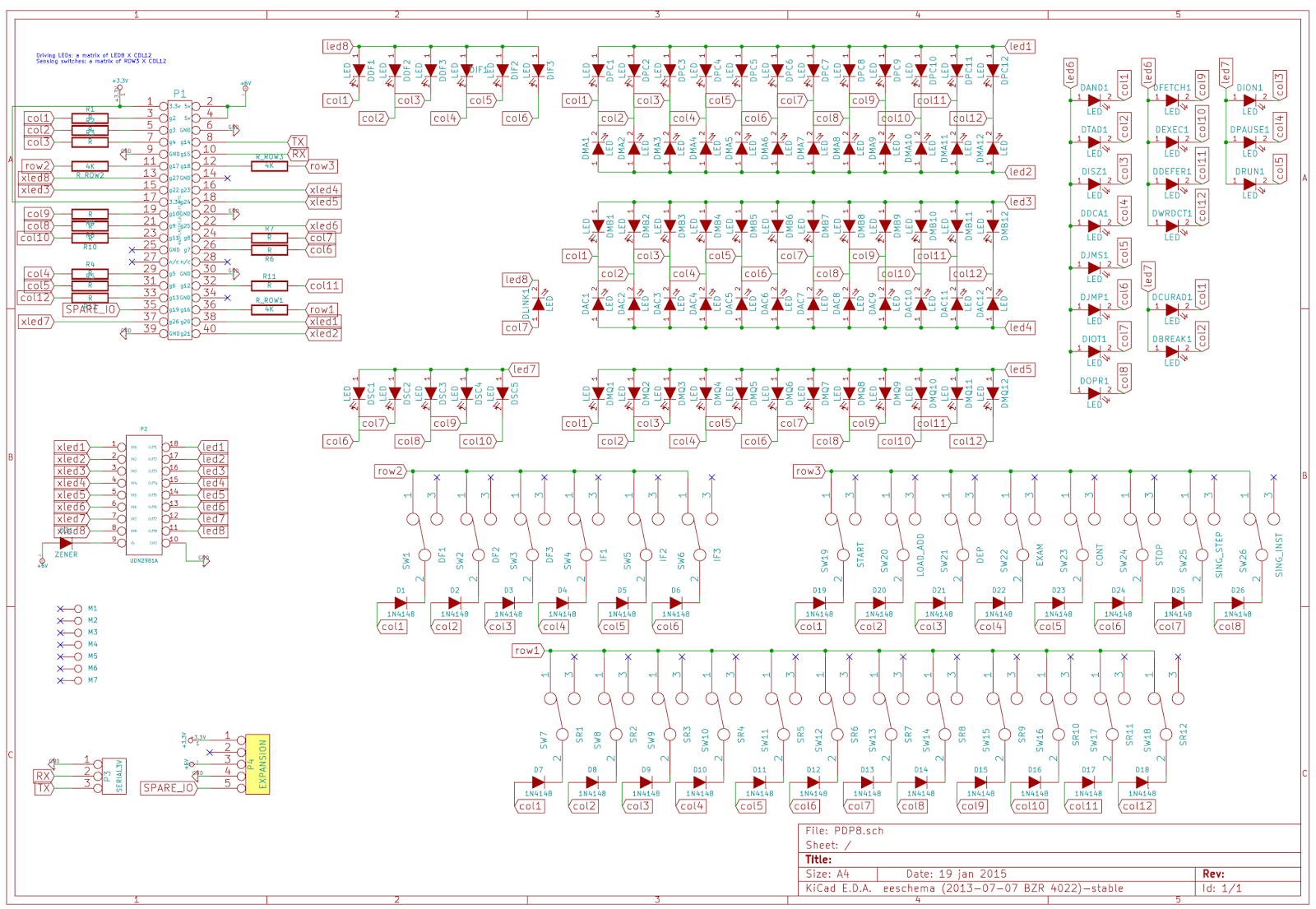
Here is the schematic (click to expand):
Quick summary: there are 3 groups of GPIO pins:
- 8 'xLED' pins, each of which provides power to the anode (+ side) of a row of 12 LEDs. The 3.3v xLED signal comes from a GPIO pin, is led into a UDN 2981A chip which switches a 5V power supply into the anode of the LEDs. I am not sure yet how much power the LEDs will need - mabe the UDN2981 is not even necessary: if 1mA of current makes a LED burn bright enough. We'll see.
- 12 'column' pins which are the cathodes (- side) of the 12 individual LEDs. So a LED is lit when a column pin is at 0V, and the LED remains unlit when a column pin is at 3.3V. The column pins then quickly flip over to being input pins for the following:
- 3 'row' pins, which provide power (actually, a power sink, active means 0V for these pins) to a row of 12 switches. The column pins above quickly get switched to input mode, and can then sense which of the switches is 'on' (causes a short to the column pin).
Note:
- The UDN 2981A actually causes a voltage drop of about 1V.
- A resistor limits the current flowing through each LED.
- A diode in the keyboard matrix (the front panel switches) avoids the problem of 'ghosting' in key matrices.
January 26, 2015
Darn, these PCB people are fast, I got the boards 3 days after they were made. The first thing I tried was a bit of a letdown: I made the holes for the switches slightly too small. So, I spent the afternoon grinding down the pins of 26 switches. The fit is not quite perfect this way, so the switches are mounted slightly irregularly, but that's OK for the prototype. Here's where progress has stopped for the day:![]() |
| PCB arrived - quickly put in a few components for a few tests. Switches will need slightly bigger drill holes in next run. |
January 28, 2015
Before plugging in a Raspberry Pi, I first tested the board with an external 3.3V power supply. Not only to check whether lights turn on and switches give a response on the I/O lines, but also to check power usage.
I discovered a problems with my PCB design:
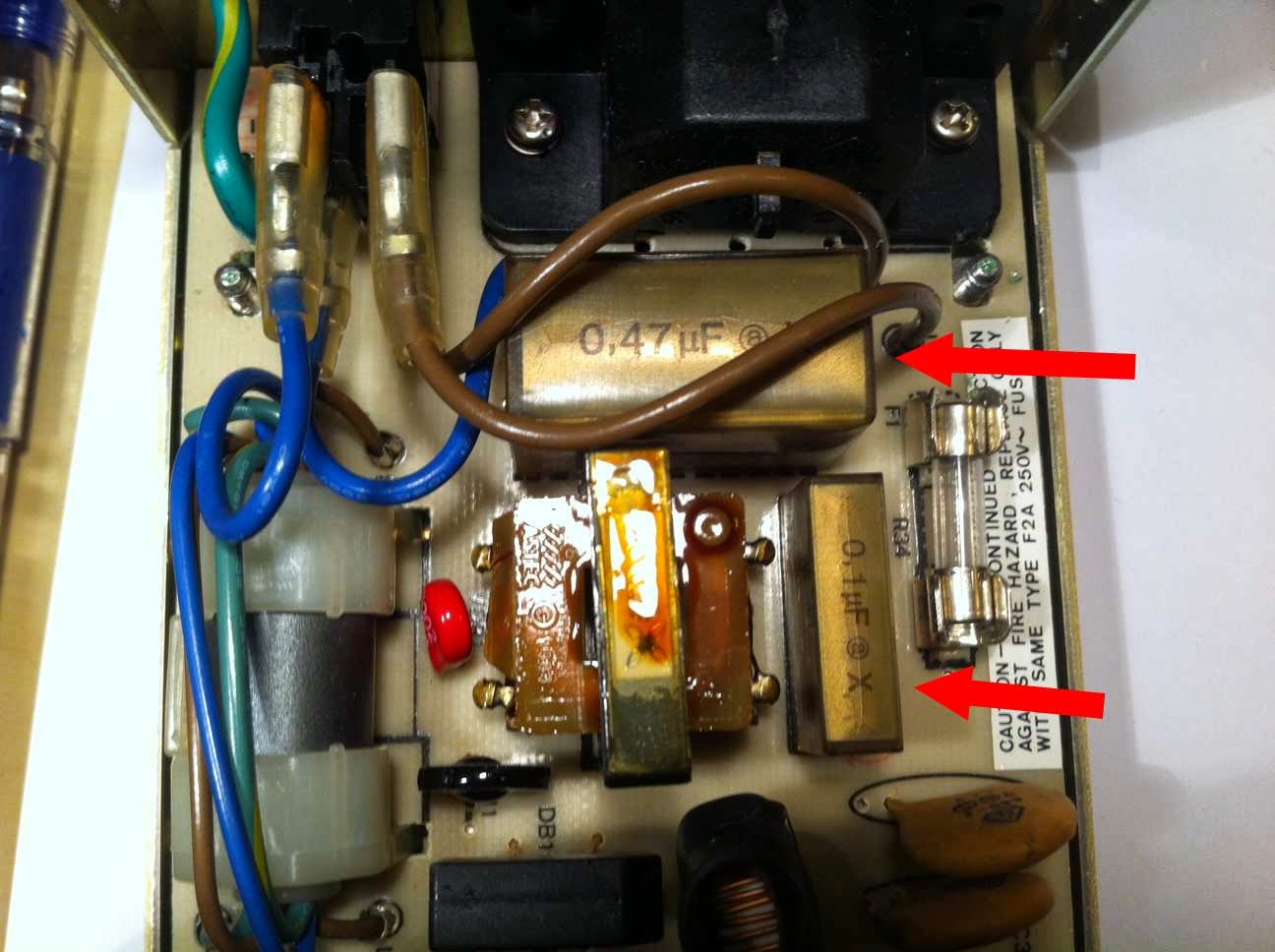
![]() |
| Green circle good, red circle bad: without adding a junction, a label doesn't create a connection |
some traces were missing! After some false accusations against Freerouting I discovered what I had done wrong: in Kicad, if you attach a net label to a line, you also need to hook it up by adding a junction. Without it, the label is meaningless.
Oh well, all problems that could be fixed manually and will be solved on the second version of the PCB.
I'm still waiting for the 2981A driver chip to arrive. It's intended to take the load off the GPIO pins - but even without that component it seems I can drive the whole board from the bare Pi itself (by shorting a few pins to let GPIO pins drive the LEDs directly). To my surprise, LEDs burn brightly enough on just 1mA of current each, using 1.8K resistors as current limiters. As only 12 of them are lit up at any one time, I stay well below the 16mA pin limit on the Pi.
So last night I finally plugged in the Pi and wrote a simple test program using the example C code from Gert van Loo (found
here). Seems to work!
Cosmetics interlude: front panel artwork
About that front panel... I had done most of its design during the Christmas holidays, which was a very anti-social thing to do really. I started off from a picture of the
8/I being restored at the RICM. The photo had one disadvantage: this particular 8/I has a non-standard OEM's label at its top, so I had to use some other photo's to reconstruct that bit. But importantly, the RICM picture was taken from more or less straight in front of the machine, so it had almost no perspective distortion.
I put that picture, 50% transparant, as a locked layer in Inkscape. I rescaled it so that each switch was exactly 10.0mm in size on the grid. My real switches are 9.5mm in width, with 0.5mm as a bit of safety between them that makes 10mm. From there on, it was a matter of measuring the spacing between the rows and columns of lights, between switches and lights, etc. I sampled each 'parameter' from multiple measurements on the photo, with a bias to the center of it (where distortion of perspective is minimal). With those same measurements, the PCB was made in Kicad.
Continuing in Inkscape, I started drawing the artwork. Lines, lettering, and the crucial Digital label. There was some real search work in store, and maybe the factoids below are of use to others trying to recreate DEC front panels:
- Font for the 'PDP-8/i' label: MicrogrammaDMedExt. This font is an exact match. Just the slash sign had to be redrawn.
- Font for al the other lettering on the panel: Akzidenz Grotesk Light. Not an exact match, but very very close. I had to adjust kerning and letter spacing and got a near-pixel-perfect match.
- Digital company logo: Ned Batchelder's site has the design history of the Digital logo. I vectorised his PNG, to use in Inkscape. This is a 'true' Digital logo, but not perfectly authentic. Because in 1968, Digital used a marginally different, hand-drawn logo on the 8/I. Not that any normal human being will spot the difference...
With the above, I was able to redraw all the components on the front panel. Working with a transparent photo of a real 8/I in the background, I could place and verify things with pixel precision. I forgot why I felt that was so important, but it seemed a Historically Responsible Duty at the time. The mind narrows when focused on tedious tasks.
I had one problem left. It's impossible to establish the right colours from web pictures of the 8/I. They're all different, because of lighting conditions etc. Fortunately, Al Kossow gave me a lead to
this DEC document, which defines the colours. DEC used colour codes that are obsolete by now, so I had to Google around to figure out how to translate them to RGB colour codes. But, for the 8/I:
- The dark brown is "Dark Luggage Tan", Munsell code 5 YR8/4, which is RGB 934f1f if this link can be believed.
- The orange is CHM4 in the Color Harmony Model, which is close to RGB b66702 if this picture is reliable.
In the above lines, I'm sure of the bold bits, but the RGB translation is done on a best-effort basis. I'll have to see my front panel next to a real 8/I before I can be sure...
I'll have to see if I made any catastrophic mistakes when I get the panel sent back from the printers. The core concern: making sure they really deliver the picture as stated, without any resizing or edge-clipping.
February 1, 2015
Life gets in the way regularly, but I finally got some time to work on the PiDP... and discovered a hardware problem: the Raspberry Pi has 1.8K pull-ups on GPIO pins 2 and 3. I did not know about them but they really spoil my party.
The final board will have two options: (1) use pins 14&15 instead of the intended 2&3. This avoids the pullup problem but sacrifices the serial port option that needs pin 14&15. (2) If anyone wants the serial port - to hook up old terminals directly - the pull-ups need to removed from the Raspberry Pi board and pins 14&15 can be freed up.
How the LEDs and switches workTo explain, first, here is a simplified schematic showing how the 3 I/O pin types work together in a multiplexing cycle. The schematic is simplified in that there are not 1 but 12 'col' pins connected to both the 'ledrow' and 'row' pins. Explanation before picture:
- During switch scanning:
- One of 3 'row' GPIO pins is set to Output Low (0V) to activate a row of switches. At any other time, the row pins are set to input (high Z).
- The 12 'col' pins (which have internal pull-ups, BTW) are set to input and will sample a Low on any pin where a switch has been closed. As long as a current sink is provided by a row pin set to Low (0V) of course.
- The 8 'ledrow' pins are out of action (either high Z inputs or Output Low) during switch scanning.
- During LED driving:
- One of 8 'ledrow' pins is set to Output High (3.3V), all the others to either input (high Z) or Output Low, both are OK. The single active ledrow pin now powers a row of 12 leds (i.e., the ledrow pin is the anode to those leds).
- The 12 'col' pins are all set to Output. Output High to leave a led unlit, Output to light that one particular led - the col pin acts as its cathode.
- The 3 'row' pins are out of action (high Z inputs) during LED driving.
![]()
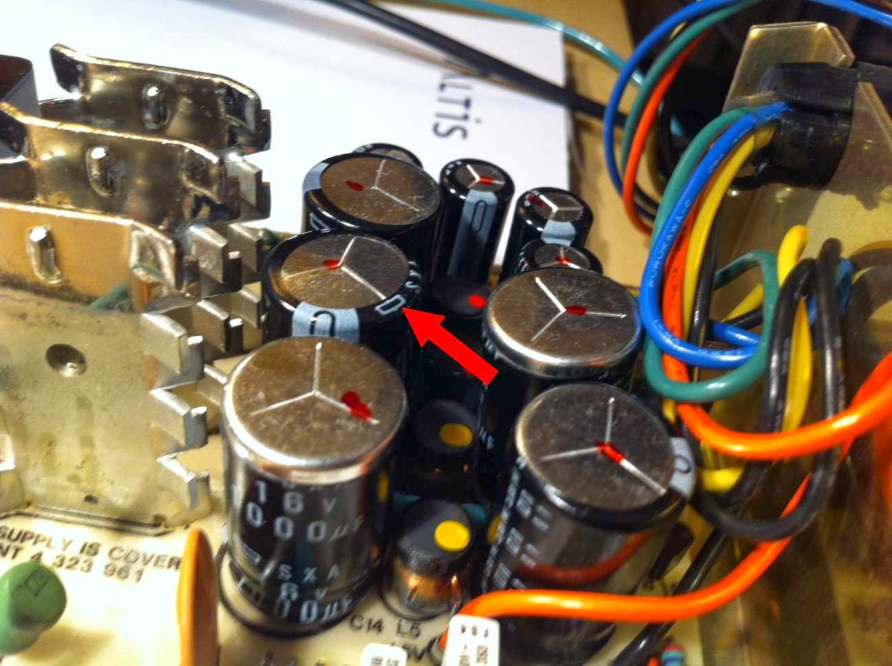
![]() |
| R23 and 24 pull up two GPIO pins which is nice for I2C but not for me. Remove them? |
Anyway. The few LEDs I have at the moment are nicely blinking along... still waiting for the big bag of LEDs I bought 3 weeks ago to fully populate the front panel.
20 February 2015: Blinkenlights are go!
Life got in the way again. But today I had some time to work on the PiDP. The new LEDs arrived and are all soldered in, annoying pins 2&3 are now moved to be pins 14&15, and I finished the test program to drive the front panel. Here is the result, in the shape of a 4 second Blinkenlights movie:
The demo program shown above consists of a normal program modifying a few global variables (think PDP 12-bit registers) in the course of its process, and a wholly separate - real-time - process that multiplexes these registers onto the front panel (think simh). The simulator program can check a variable for the current switch positions at any time and will adjust the register values of the top three led rows to reflect their settings.
In other words: I'm ready for inserting the multiplexing process into simh. Yay!
On the hardware side, there's one thing still to do: insert the newly arrived UDN2981 chip which will take the load off the ledrow pins of the Raspberry. The load of lighting 12 leds at a time, with the current resistor values, is actually not a problem for the Pi and so I let the Pi drive them directly from its own pin power. But if you want the LEDs to burn brighter, the 2981 is needed to provide the juice.
To be continued. May the Blinkenlights be with me.
![]() |
| Souree: Vince Slyngstad's DEC site |
February 21, 2015: Flights of fancy
As it turns out, there is a freely available 3D model of the PDP-8/I switches. It looks like I can change its bottom half to become a push-on cap to fit my switches. Hmm.
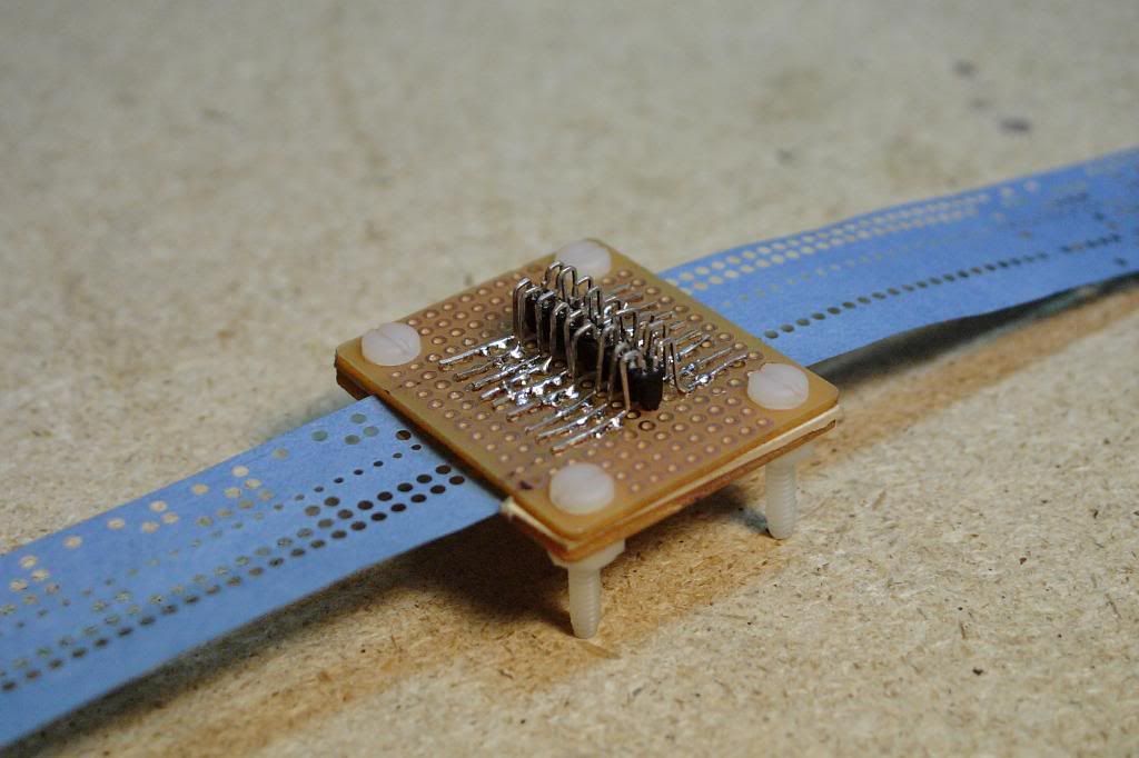
Also, I figured out that I can add a paper tape reader on the PCB with a relatively modest extension of the schematic - as done by
NeXT on his blog on vintage-computer.com. Add 9 IR receivers (and 9 IR leds), hook them up as an extra 'switch row 4' with the one spare GPIO pin I still have, and you can sense 9 paper tape holes.Users will need to pull the tape through manually. The one big dilemma is how I get punched paper tape to begin with. Allowing users to
print outpaper tape with holes being black dots would be a great solution. Then, the PiDP could print paper tape on A4 pages, the user having to cut it up in strips to read it back again. But no idea whether IR receivers can shine through paper and detect black vs white on the paper... I ordered some to play with anyway.
Back to reality tomorrow: get simh to work with my multiplexing function.
February 22, 2015: simh blinks my leds
With only 30 lines of code inserted into simh's body of code, and adding my gpio.c multiplexing driver to simh, I now have a real (real emulated) PDP blinking the lights of my front panel. That was way easier than I expected. Well, all simh is driving so far is the PC row, but the other lines should be easy. Tomorrow. Or actually, later today. I love late weekend nights.
February 24, 2015: Progress
Meanwhile, I got simh to run and blink pretty much all of the front panel leds, except a few where I need to figure out their exact behaviour in real 8/I's first. A few of the switches are working too.
Next to that, I wasted a few hours completing a second prototype. Given that I had to order a few boards anyway, I populated one of the others I got back from Elecrow. This time I used 5mm leds, instead of 3mm leds. I think that's an improvement. Also, the 2981A provides extra brightness to the leds and works as intended.
Because I stupidly made the solder holes too small to fit the switches I want to use, I had to grind all the switch leads down to size for the first prototype. This time, I just used smaller switches. Which looks a bit uglier, but it was worth a try... Anyway, the pictures below give a good impression of how the raw board will look. Instead of the white-on-black acrylic front panel, I temporarily use a black-on-white paper printout...
![]() |
| Second prototype, back side. Note the Raspberry Pi Model A+ and quite a few fixes to the PCB :) |
![]() |
| I guess it will need a proper enclosure... |
![]() |
| I used small switches on the second proto - does not look right |
![]() |
| ... but the larger 5mm leds I used this time do look good I think, |
![]() |
| Here's prototype 1. Right-sized switches, mounted a bit irregularly :( |
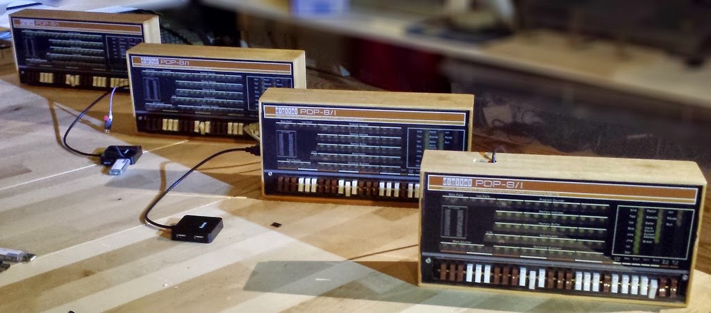
February 26th, 2015: Booting OS8 with a working switch panel
Works! There are some finer details to finish in the switch handling, but all the front panel switches behave as they should except under some 'corner conditions' that need to be ironed out.
After finishing up today, I brought the two prototype PiDP-8s to our local hackspace/
vintage computer meet and we booted up OS8. Jos, our very own PDP expert - if I may say so - kindly brought along some paper tapes with the BIN loader and FOCAL. As well as a nice small handheld paper tape reader (can be seen between the pair of glasses and the right-hand PDP) I think I can clone into the PiDP. Some day...
![]() |
| A night at the Hackspace. OS8 on the screen and the panel switches work :) |
Priority now shifts to getting the acrylic cover plate. The temporary paper one is getting on my nerves.
February 28th, 2015
Unexpectedly quick, some IR leds and photodiodes arrived. So I put together a crude prototype of a paper tape reader. I started with the
design of NeXT at the Vintage Computer Forum - replicating his idea of two rows of photodiodes, and bending their pins to make them stand upside down. But thoughts have progressed a bit on the electronics.
Rather than NeXT's purely electronic approach (converting diode output to TTL signals with 4093s), I'm going to try a software-based solution with an Arduino Pro Mini. That is a bit heavy-handed - a whole MCU instead of 9 NAND gates - but it requires just 1 IC, versus 2-3. The atMega would anyway be needed if the thing is to deliver serial output as well as parallel, and sampling photodiodes using analog pins means the atMega MCU can help to make readings more reliable (self calibrating routine, etc).
One problem stood in the way of the Arduino idea initially: the atMega has only 8 analog inputs, and there's 9 holes to scan on paper tape. What I'll try is scan for an index hole first, then - once one is found - quickly scan the 8 data holes, repurposing the 'index' analog pin to sample one of the 8 data holes. I think that should work. Anyway. The picture shows the test contraption I cobbled up today. No idea if it will work - I guess we'll see tomorrow...
February 29th, 2015
I put the paper tape read into Kicad - still a draft. Note: the board breaks in two, the top half folds behind the bottom half. The paper tape is led past two horizontal pin header rows. Sounds like it could damage the tape, but is fine in practice. So far. Making a board is not the same as having a working device :)
Warning- schematic contains an error - fixed by now...March 2nd, 2015
I finally,
finally, finished the artwork for the acrylic panel and sent it off to a manufacturer in Germany. Size is 30x14cm, a 2:3 scale replica of the 8/I. The reproduction is pretty much pixel perfect, with the exception of the bottom brown/white color bar being moved a few mm down from the original for a better cosmetic fit.
The panel has 65% translucent slots (marked in grey) where the indicator leds sit behind and will be done in 1200 dpi (not that anything beyond 600 dpi is noticeable, but still nice). Now I've got to wait 10 days for the test batch of 5 pieces to come home... Note that the big black void at the bottom is where the switch panel is fitted. Looks weird without them.
Meanwhile, I spent time on the paper tape reader. Alas, the prototype I cobbled together on perfboard performs rather ho-hum so far. I guess I better hold off until I am sure this is the right way to go.
March 5th, 2015
Over the past two days, I spent some time thinking of some practicalities if this is to become a kit.
First, what should it be? A 'bare bones kit' consisting of PCB, acrylic front and electronic parts? Or a nicely packaged gadget that is packaged beautifully enough to grace a geek's living room without objections from the loved ones?
Enclosure... I'm considering to include
this one as an option for the kit. The cool thing is that it is also available in a half-size case that would fit the paper tape reader in a matching box.
Free from cables... I'm starting to work towards the idea of a nicely cased machine, which can be wholly stand-alone - no wires at all. Of course you
can still use HDMI, USB keyboard/mouse and USB storage, why not. But it could also just use a Wi-Fi connection for terminal sessions and any other communication to the outside world. Heck, you could stick a $16 LiPo battery in the back of the box and make the PiDP just as portable as a laptop.
Dual-mode... The PiDP should be a straight & pure PDP-8 replica in one mode, but still be useable as just a normal Raspberry Pi in a fancy case in the other mode. Why not? During boot time the position of the STOP decides whether or not to be a PDP-8.
Secondly, I brought a very good idea back from one of the guys at the hackspace meeting last week. It's hard to mount the 26 switches perfectly aligned - unless you remove the turning pin from each switch, and string them along on a long brass rod that holds them together. Like pieces of beef on a barbecue skewer...
It turned out to be brilliantly simply: with a side cutter, snip off the end of the pins, pry out out the pins with a 2mm screwdriver and stick the switches on the brass rod. Which turned out to cost only $2 at the local DIY store.
So, the easy-to-mount Switch Skewer looked like this, before I proceeded to stick the whole thing into my prototype PCB no. 3, and soldered it together. Worked perfectly, looked great. But next time I need to remind myself to solder the #%$# thing on the front side of the PCB, not the back side! Oh well. Prototype #3 will not see the light of day then.
Tomorrow, it's time to pull out prototype board no. 4 and try again. Because when the acrylic panel comes in next week, I want a near-perfect-looking machine for a Youtube demonstration. Prototype #1 is no good because of the irregularly soldered switchesand its smallish 3mm leds. Proto #2 is no good because although it used better-looking 5mm leds (a matter of taste, 3mm leds are the scale-correct size actually), it used a smaller switch type I had lying around.
Lastly, I also started to do a first cost estimate. If I get some quantum discounts, a $100-120 kit cost is feasible. But I'd need to do a run of at least 100 units, especially the acrylic panel and switches then go down dramatically in cost due to bulk pricing. Not sure if there are enough geeks in this niche to do 100 units though. Have to reality-check that sooner or later. Everything will have to wait till next week anyway, when I get some time to work on the project again.
March 9th, 2015: Going to VCFeX to demonstrate the PiDP
I got a really kind invitation from one of the DEC exhibitors at the
VCFeX to come and join the PDP-8 'pavillion' there. The VCFe has a bit of a PDP-8 theme this year, with the 50th anniversary of the Straight Eight. So I
signed up for what will the debut of the PiDP, where it will run next to a real PDP-8/I amongst others. That'll be an acid test. Nice.
It also gives a very useful deadline to wrap up the software and mechanical construction of the prototypes. Anxiously awaiting delivery of the sample case and acrylic panel to see how they've turned out... always feels like it takes forever when you're waiting for stuff.
The one major challenge is how to cut the acrylic panel: it needs a slot cut into it to accommodate the switches, and I also need to shave off 8mm to fit it into the case I decided to use. Sounds simple, but cutting *clean and straight* slots in acrylic is something for which I lack the tools. Time for a social visit to a few of the local cabinet-makers...
March 19th, 2015: Polishing up the software
I spent quite a few hours to make the modified simh a bit more invisible. Meaning the Pi automatically boots into PDP-8 mode unless the user has enabled the STOP switch at boot time.
![]() |
| The original 60s tape labels on USB sticks that now think they're punched paper |
And also, the way simh normally deals with emulating paper tape readers and disk drives is efficient but, err, unromantic. Meaning you have to step out of emulation, type 'attach ptr binloader.bin' and 'go' to continue emulation.
That is not OK for a replica. So I made it such that you take a USB stick, put a disk image or paper tape image on it, and then you stick it in to the machine. You hit the SING_STEP and SING_INST switches at the same time, and whatever image is on the stick is auto-mounted. The nice thing is that now, USB sticks are just modern replacements for paper tapes or disk cartridges! The form factor is different, but plugging in the BIN Loader stick and hitting the two switches does exactly the same as putting a paper tape into the paper tape reader and powering the device on. It's great fun! (I think).
Here's two USB sticks with the BIN Loader and FOCAL69. You toggle in the RIM Loader, plug in the BIN Loader
tape stick, toggle 7756 LOAD_ADD, START to load it. Then plug in the FOCAL69
tape stick, toggle 7777 LOAD_ADD, START, and run from 0200 after the Focal
tape stick is loaded. You truly have nothing to do with simh commands, it's pure PDP-8 this way.
I'll polish it up a bit more, but it's charming. It also makes it very attractive to have a small USB hub plugged into the PiDP. Then, one of its USB slots is the paper tape reader, two are disk drives, one is maybe for a hard disk cartridge. It works with all the devices that simh emulates, so it invites experimentation. Think USB DECtapes!
Lastly, I'm toying with a program which enhances the uselessness of the whole machine a bit more. The idea is that the Pi can be booted up in Pi mode as well as PDP mode, in which case it's just a Pi like any other. But the front panel will show - in glorious octal - the time, day, year, as well as the weather (barometric pressure, cloudiness, temperature) for the coming 7 days. The weather data is just taken from the rather nice Weather Underground API service. Not sure if I will finish this particular folly, but it fits with my idea that the PiDP should be pretty enough to be a display item. And reading the time in octal will make it an exquisitely obscure time piece as well as good training for rusty PDP users.
March 20th, 2015: Finally Front Panels
It took 20 days, but the manufacturer finally sent me the 4 acrylic front panels. They turned out beautifully. I built myself a router table last week to be able to fit the acrylic panels into the cases. Taking only the first two panels as guinea pigs, I did only marginal damage to them before they fitted in.
But for cutting the slot for the switches into the acrylic panel, I do need to find a way which does not involve me. Or figure out how to do this efficiently. I'm just not very patient with this kind of handywork.
The other thing that will need experimentation is the white mask behind the acrylic. Remember, the acrylic is actually a translucent image. That's done so the leds can be seen behind it, but the white lettering should obviously not be translucent - it still needs a white mask behind it.
Tonight I experimented with just spray-painting the back of the panels with white paint, masking off the led slots with tape to keep them transparent. It proves to be a rather tedious process because of the 0.5mm tolerances in some places. So tomorrow I'll experiment with plan B: using a heavy paper mask with led cutouts, and glue that onto the acrylic's back in an orderly fashion.
![]()
I'm so happy after the long wait, that I took some intermediate pictures which serve little purpose because they're not especially pretty. But, shown above is the acrylic panel with a temporary paper backing (so the led slots are all white), fit into the case. I did not even take off the blue cover film, which makes the edges looks a bit rough. Rest assured, the acrylic is cut very cleanly once you peel off the film.
On Sunday, I hope to wrap up three of the prototypes behind their acrylic panels, in their boxes, all done for a demo movie. Getting there!
22 March 2015
It's there! At least, the first fully cased prototype is. A lot of small things to improve in the next three prototypes in the coming week, but:
![]() |
| Cased in ts 15x30cm box. I finally got around to spray-painting the switches... |
![]() |
| It has a nice 60s look to it, I think |
![]() |
| Shown with its all-in-one peripheral: a USB hub in which one port is PTR, two are disk drives, one is disk cartridge. |
![]() |
| You can see a few DIY mistakes I made in cutting the acrylic. And it needs black screws. But it looks sweet! |
30 March 2015
Things progressed nicely over the last week, with three prototypes finished. They vary in their connectivity: Two use a Raspberry Pi Model B+, and thus have a side panel with Ethernet and 4 USB ports brought out. One is WiFi-only, using a Model A+ inside. A fourth and last one will have an old-style serial port brought out so serial terminals (I've got an ADM-3A waiting) can be used. This does require removing two SMD resistors from the Pi though.
Here is a Youtube movie of Prototype #1 running: http://youtu.be/5hyUActgT2ESome points to note:
- I still have to verify all the LEDs respond exactly as they do in the real 8/I - I believe so but the real test is at the VCF East!
- You'll note that those switches that are momentary toggle switches in the original are still 'flick on/flick off' in this prototype. I'm planning to put some springs in these switches to make them momentary - it's not hard to do. But to be honest, you get used to this so quickly it's not very high priority. The front panel software converts a on/off toggle into a momentary signal anyway.
- Also, the STOP switch is meant to be upside down from all the other switches (off = down). I let it be inversed - off = up - for the moment, it's a setting in the code but I prefer it this way myself.
- This particular PiDP uses a Raspberry Model B+, and I'm running a normal Ethernet cable between a laptop with PuTTY and the PiDP. Works flawlessly! No need for crossover cables.
Next steps: refine the software a bit more, and start collecting a nice library set of PDP-8 software from all of its development stages. Especially, I'd like to try TSS-8. And work on the final web site and manual (I believe in good manuals).
After VCF, I'll probably need to polish up some imperfections that are bound to crop up when I run the PiDP next to real machines. And start planning for the kit. On that front, I got a spot of (somewhat) bad news: the really good German manufacturer I used for the acrylic panel seems to have stopped doing them. So I need to find someone else that wants to do it for a reasonable price... oh well.
April 10, 2015
All dressed up and ready for the VCF.
Well, there they are, the four prototypes:
I played around a bit with connectivity options. So two PiDPs use a Raspberry Pi Model A, the other two a Model B. The machine in front has a slot on top to access the HDMI monitor connector (slot not necessary with the right HDMI cable, BTW), the other machines only run terminals from serial or network terminals which is all you need.
- The Model A's have the serial port enabled (meaning R23&24 were clipped off from the Pi's).
- To connect a modern laptop, use a USB-to-TTL-Serial cable. The PiDP runs happily off its 5V power pin: a neat plug & play solution without need for a power supply!
- To hook up a vintage serial terminal, you need a TTL Serial-to-RS232 converter, and a 5V power supply (a laptop's USB port can provide the power too).
- All four PiDPs have a micro WiFi adapter plugged in, so you can log in to PDP terminals that way too - or use WiFi with VNC to run the Pi's desktop GUI concurrent with the PDP-8 terminal...
- The Model B's are left unmodified, so their serial port is not enabled. To make up for that, the B's can also be accessed from a laptop using an Ethernet cable. Because Model Bs have four USB ports, a separate USB hub is not necessary - but it's still nice to add.
My recommendation after all of these variations: slight preference for the Model A. With a USB hub and micro WiFi, it does exactly the same as a Model B - except for an Ethernet port you won't miss with WiFi.
Adopt-a-PiDP...
My better half has decided that our suitcases will be filled with more important things than PiDPs on the way back home from VCF East.
So if you're at the VCF and want to take one of these PiDPs, please let me know :) They are 100% compatible with the future final version of the board, they just have some manual fixes on the PCB.
Preparing for producing a batch of PiDP kits...
The company who made the four test panels does not want to do any more of them... apparently they had to redo the PiDP panels three times before they were OK. I found two other manufacturers, who charge $15-20 more - the bad news - but will deliver them ready-made with the white mask and CNC-cut switch slot. Which is good news. Because in this project, I hated nothing more than using the router to cut a slot for the switches. Except for painting the panel backs whilst staying clear of the transparent windows. Well worth the $15 to outsource those two chores I think.
But with this, the kit price would end up at $135 instead of the earlier $120. Whilst the bet I had going against myself in January was actually to do it for $99. Hmm. Inflation. There's still time to haggle on the panel cost a wee bit more though.
May 7th, 2015
Production of the kits has started. Well, at least I've ordered all the parts except PCB and acrylic panel. I still need to decide where to produce the acrylics, it's proving to be more cumbersome than I thought. But it'll happen any day now.
In the mean time, I got extremely lucky: today, thanks to PDP collector hb9aik, an original PDP-8/I front panel found its way to me. Not only that, it's in near-perfect condition! Never thought this day would happen, so thank you!
Here's a shot of original-vs-replica:
So, the next project coming up is already defined: add the PiDP circuitry behind the 8/I front panel. Strangely, this is the one and only 8/I I've ever seen in real life. Very useful, as now I can see the orange of the PiDP needs to be brightened up a bit. It's very subjective of course, but I was surprised that the toggle switches on the replica actually have a better feel to them than the originals. Just not nearly as pretty. The switches of the 8/I feel very different than the more familiar toggles on an 8/e, for instance.
What a glorious day... a real PDP-8/I. Well, the front bit of it anyway.
May 20th, 2015 - spacewar!
I've been busy getting all the parts together for a run of kits. The acrylic seems to be in production with a good manufacturer in Holland - at least, it will be tomorrow after some last-minute questions I got from them. The other parts started to come in bit by bit.
![]() |
| The first peripheral for the PiDP... |
![]() |
| spacewar! As seen on the PiDP :) |
In the mean time, I ordered a small 7" HDMI screen from China, and mounted it in the one PiDP case I still had left over. The 8/I is a rackmounted machine, so I might as well have something on top of the PiDP (this vc8e type oscilloscope display being that something) and something below it (papertape reader maybe?). 3 stacked cases makes a rack-mounted system of sorts.
But the real reason for this subproject is Kyle Owen's PDP-8 implementation of
spacewar, which I saw at VCFeX. It ran on vc8e-like
hardware that he developed for his 8/M, using an oscilloscope screen.
But then Kyle mentioned he'd had an emulation of all this goodness running on SimH and Processing... See his
Youtube demo. That's a must-have for the PiDP! I just got the HDMI screen running, and played my first PiDP spacewar match. Alas, not using the HDMI screen, it seems that Processing on the Pi has some nasty problem with OpenJDK. So I used a laptop over WiFi as the screen. Never mind - just now, I played my first spacewar game ever. On the PiDP. Thank you Kyle!
May 29th, 2015
I rewrote Kyle's vc8e screen emulator in C, using openVG to get it fast enough for the Raspberry Pi. It works nicely now, so the PiDP starts to look like a proper miniature rack of instruments! The code needs to be cleaned up, but it's there. Once I get the final PCBs in, I'll hook up handheld controllers to the expansion port.
For the rest, not much to mention. The first sample of the acrylic panel came back from the new manufacturer, it needs redoing because the colours are a bit off. But that'll be done. Almost all other parts are in for the first run of 250 kits, with only the non-standard GPIO headers (they need to be extra tall for the Pi) and the cases still in transit. Also, it's high time to clean up the install scripts for the PiDP. That is the one thing I keep postponing...
 Outside of the UK, these machines are little known. They were introduced in the early 90s by Amstrad as no-frills pocket word processors, long after the era of the Z80 had come to an end. It seems they were popular with the same people that Amstrad catered for with their PCW range, and were frequently used in education it seems.